This is the official displacement pump parts diagram for the Graco Ultra Max II 695, decoded from Graco's own instructions-parts list manual. Each numbered callout — Ref. 12 through Ref. 222 — maps to a specific component, with the pump itself at Ref. 18, secured by mounting screws at Ref. 17 torqued to 50 ft-lb (68 Nm). A packing repair kit (part 239939) bundles the most commonly serviced components together.
This breakdown decodes the official Ultra Max II 695 displacement pump diagram straight from Graco's instructions-parts list manual, matching real reference callouts to genuine part numbers.
1. The Pump Assembly Callouts
| Ref. | Component | Notes |
|---|---|---|
| 12 | Connecting Rod Assembly | Aligns with the piston rod hole during pump installation |
| 14 | Pin | Pushed in after aligning the retaining spring during install |
| 15 | Retaining Spring | Pushed up with a screwdriver before the pin is inserted |
| 17 | Screws | Mounting screws, torqued to 50 ft-lb (68 Nm) on installation |
| 18 | Pump | The complete displacement pump — see full repair procedures in manual 308815 |
| 222 | Piston Rod | Positioned at its lowest point before flushing/pump removal |
Graco's manual notes that Packing Repair Kit 239939 bundles several reference-numbered components together — worth ordering as a kit rather than piecing together individual ref numbers when a rebuild is needed.
2. Drive Housing & Frame Callouts
| Part | Part Number | Applies To |
|---|---|---|
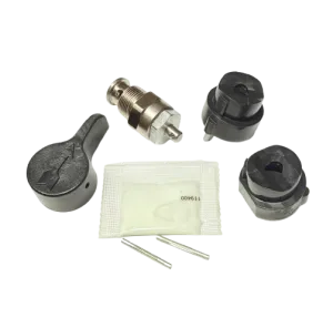
| Drive Housing Kit, U-695 | 240057 | Model-specific to the U-695 platform |
| Spring Clip | 192648 | General hardware, complete sprayer parts list |
| Thrust Ball | 100069 | General hardware, complete sprayer parts list |
3. Drain Valve Callouts
| Ref. | Component | Part Number |
|---|---|---|
| 53 | Pin (handle) | Driven out to remove the drain valve handle |
| 54 | Handle | Turned to closed position before pin removal |
| — | Drain Valve Assembly | 235014 |
Per Graco's manual: relieve pressure first, then unscrew the spring retainer from the valve body, remove the spring/washers/stem-ball, and clean debris from the ball and seat area before reassembly. Skipping the pressure relief step is the most common safety oversight during this repair.
4. Pressure Transducer Callouts
| Ref. | Component | Installation Note |
|---|---|---|
| 67 | Pressure Transducer | Lightly grease or oil before installing the pump |
| 69 | Transducer Seal | Heat in hot water for several minutes before installation; avoid excess pressure from probes or fingernails, which damages the packing |
5. Pump Removal Reference
- Relieve pressure completely before starting any pump work.
- Flush the pump if possible.
- Stop the pump with the piston rod (Ref. 222) in its lowest position.
- Loosen the screws (Ref. 17) and remove the pump (Ref. 18).
- For full step-by-step repair instructions once the pump is out, consult Graco's dedicated displacement pump repair manual, 308815.
Shop Genuine 695 Pump Parts
Find the packing repair kit, drive housing kit, and related pump components for your Ultra Max II 695.
Shop Ultra Max 695 PartsShop the Parts You Need
Frequently Asked Questions
What is Ref. 18 on the Ultra Max 695 pump diagram?
The pump itself — the complete displacement pump assembly, secured by mounting screws at Ref. 17, torqued to 50 ft-lb (68 Nm).
What does the packing repair kit include on the 695?
Part 239939 bundles the reference-numbered components that make up the pump's packing set — Graco's manual marks which ref numbers are included so you can confirm before ordering.
How do I remove the pump on an Ultra Max 695?
Relieve pressure and flush the pump, loosen the screws at Ref. 17, and remove the pump at Ref. 18. Full procedures are in Graco's displacement pump repair manual, 308815.
What torque spec is used when reinstalling the 695 pump?
The mounting screws (Ref. 17) are torqued to 50 ft-lb (68 Nm) per Graco's official instructions.